Controlling a Launchpad Smart Car with iOS

Controlling a Launchpad Smart Car with iOS
About This Blog
This is a guest blog from one of the many folks who are using techBASIC in the lab, school, business or home for technical programming and, in this case, controlling external devices. We’re excited to provide a forum for them to share what they are doing in their own words. If you would like to see your own project here, get in touch with us at support@byteworks.us.
Contact Leo Estevez with your questions about this project or the related KickStarter project.
The Car
This blog builds on the BlueRadios blog which shows you how to use techBasic with the BlueRadios BLE module. In this DIY example, we connect an MSP430 Launchpad to the BlueRadios module which is running an Arduino Like Virtual Machine called REKAM1 that works via simple text messages.
Parts List
Here are the list of parts you will need for this project:
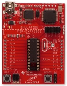
MSP430 Launchpad (includes a micro-controller and a USB interface to program it form your PC)
http://www.ti.com/tool/msp-exp430g2
BlueRadios S2A Module (includes a Bluetooth Low Energy Radio for communication with your iOS device). Some of the photos show the prototype board, but either the full board or the smaller module shown here will work. The pinouts are the same.
http://www.digikey.com/product-detail/en/BR-XB-LE4.0-S2A/822-1017-ND/3593638
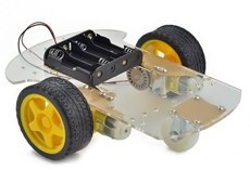
2WD Smart car chassis (includes two motorized wheels, a third wheel, and the base). You can also use the 4WD version, shown in some of the photographs.
http://www.amazon.com/gp/product/B00GLO5SMY/ref=oh_details_o06_s00_i00?ie=UTF8&psc=1
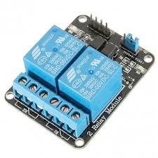
2 channel relay module (includes two power relays that enable the micro-controller to control electricity going to the two wheels of the smart car chassis)
REKAM1 Download (enables simple text messages to control micro-controller pins)
Wednesday, March 19, 2014


Assembly
You'll first need to assemble the smart car. The motors should be fastened to the base with the right angle braces. The caster should be attached with the long mounts and the battery holder should also be mounted as depicted in the link above.
Next, you will need to attach the BlueRadios module. The BlueRadios module is connected to pins 3 and 4 of the Launchpad headers which correspond to the UART Rx/Tx. CTS and RTS from the Blue Radios module should be connected to pins 8 and 9 of the LaunchPad. Ground and Power for the BlueRadios Module also need to be connected to the GND and VCC labeled pins on the Launchpad.
Wednesday, March 19, 2014
Next, you'll need to fasten the relay module with a screw to the base and solder or jumper wires from the two input pins on the relay module to pins 2 and 14 of the Launchpad headers.
The two through holes beside the USB connector on the Launchpad are Ground and 5V/6V. These should be connected to the battery holder and this 6V should also be connected to the one side of each motor. The other side of each motor should be connected to each of the power relays with the normally open(NO) side connected to ground.
The assembled system will look like this:
Next, you will need to program your Launchpad via the provided USB cable with the REKAM1 Virtual Machine. The project code can be found here:
Instructions on how to import and existing project and flash your Launchpad can be found here:
http://processors.wiki.ti.com/index.php/Importing_Projects_into_CCS
Next, we need to make some modifications to the BlueRadios example. First we need to ensure the module is set to data mode:
! Set the mode to data mode.
! value = [2]
value = [1]
Next, we want to use the accelerometer to enable us to control the drone, so we'll need to initiate this sensor:
! Let the user type a command, sending it to RX.
sensors.setAccelRate(0.1)
a = sensors.accel
Next, we want to initialize both wheels on the car to a pulsed output percentage on time of zero:
line$ = "put 2 0\n"
line2$ = "put 14 0\n"
We need to send the newline character(\n) above so that REKAM1 knows this is a separate command. We're going to send two lines of code at a time since there are two wheels to control. Next we write a condition for moving forward:
IF a(2) > .40 THEN
line$="put 2 70\n"
line2$="put 14 70\n"
PRINT "FORWARD"
END IF
In the above, we are checking to see if the magnitude of the accelerometer in the second of three dimensions exceeds some threshold. As we tilt our iOS device, the magnitude of accelerometer values will change depending on how much of that component is aligned with gravity. (we're always accelerating down) We can now add conditions to turn off either the left or right motor when we also tilt the iOS device left or right:
IF a(1) < -.2 THEN
line$ = "put 2 0\n"
PRINT "RIGHT"
ELSE IF a(1) > .2 THEN
line2$ = "put 14 0\n"
PRINT "LEFT"
END IF
Finally, we need to add some code to send a second line of code(line2$) so that the left and right wheels are actuated for every program loop. This code converts the text message we want to send into an integer array that we then write as a characteristic over our Bluetooth Low Energy Peripheral connection:
DIM line%(LEN(line2$) + 1)
FOR i = 1 TO LEN(line2$)
line%(i) = ASC(MID(line2$, i, 1))
NEXT
line%(UBOUND(line%, 1)) = 13
blueRadiosPeripheral.writeCharacteristic(ch, line%, 1)
You can see some videos of a text messaging robot game with a similar smart car kit I put together for a Kickstarter here:
https://www.kickstarter.com/projects/2105764235/rekam-dr1-smartphone-programmable-car-program-on-t
The complete techBasic code described above can be found here(and in future releases of techBasic): SmartCar.bas
This kit basically integrates an MSP430 with some PowerFets, a BlueRadio module, a Smart Car kit, 50 K'nex pieces, some sensor and servo attachments with a modifiable robot game written in techBasic! I developed this kit and game to make learning about programming truly fun. Enjoy!

